Manufacturing Engineering
End-to-end factory design, validation and process planning from concept layout to virtual commissioning
Layout & Facility Planning
Design and optimise your factory layout in 2D and 3D.
Facility Scanning (LiDAR)
Millimetre-accurate 3D scanning using FARO, Leica or NavVis.
Scan To BIM
Convert point cloud data into LOD-standard 3D models.
Process Planning
Define operation sequences, tools and MBOM from station to plant level.
Throughput Simulation (DES)
Simulate production flow to optimise JPH and identify bottlenecks.
Dynamic Simulation & OLP
Validate robot and human movement virtually commission machines.
Ergonomic Analysis
Identify unsafe operator movements before shopfloor implementation.
Kitting Rack Design
Design kitting racks and trolleys for optimal parts visibility and workflow.
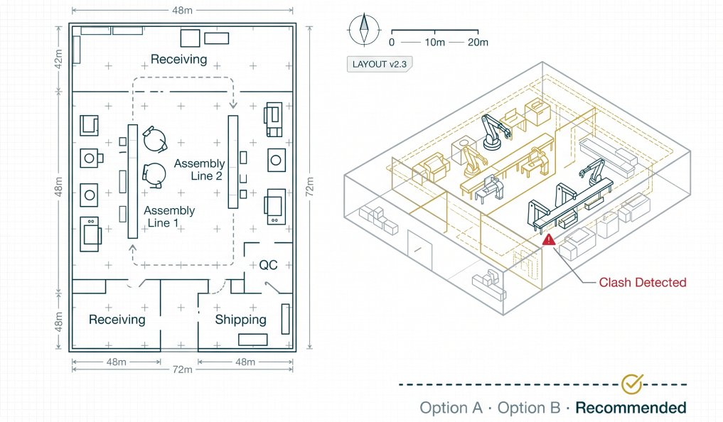
Layout & Facility Planning
Design and optimise your factory layout with digital precision in 2D and 3D
Design your factory layout aligned with production strategy, process sequence and material flow visualised in both 2D and 3D. We detect collisions and clashes between all factory elements (machines, conveyors, robots, utilities) in a federated digital model before any physical work begins.
Deliverables
- Digital assembly sequence aligned to production strategy
- Space utilisation analysis and material movement route planning
- Collision and clash detection report (all factory elements in federated model)
- Alternate layout proposals and recommendation report
- 2D and 3D visualisation of the complete factory layout
Use Case / Client Example
An automotive OEM was expanding a body-in-white line and needed to validate whether two new robot stations would fit within the existing structure without clashing with overhead conveyors. CY4 built the complete federated 3D model, detected 6 clash zones and proposed an alternate station arrangement saving 3 weeks of physical trial and ₹18 lakhs in rework cost.
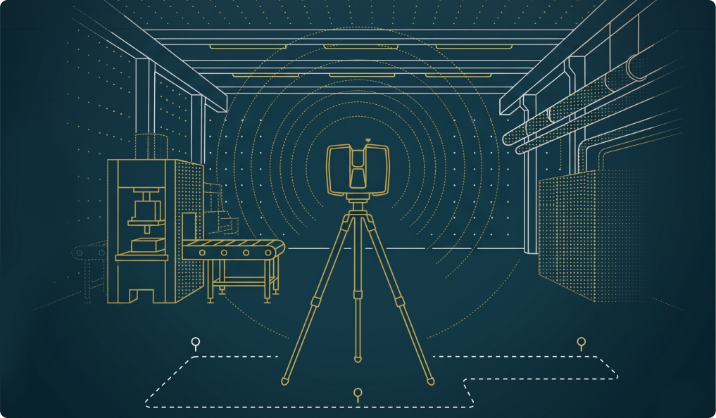
Facility Scanning (LiDAR 3D Scan)
Capture your factory as it really is millimetre-accurate, in hours not weeks
Capture your existing facility with millimetre-accurate LiDAR scanning using FARO, Leica and NavVis scanners. The output is high-fidelity point cloud data the foundation for all digital validation, 3D modelling and as-built analysis work. Mobile scanning with NavVis enables full factory coverage in a single shift.
Deliverables
- E57 / RCS / XYZ format point cloud output compatible with all major CAD and BIM platforms
- Panoramic imagery of entire facility for visual reference
- Noise-removed, stitched scan data ready for 3D modelling or direct analysis
- Scan accuracy: ±2mm suitable for clash detection and deviation analysis
- Facility coverage report with scan station map and coverage verification
Use Case / Client Example
A Tier 1 supplier needed a complete as-built digital record of a 28,000 sq ft paint shop before a planned renovation. CY4 completed the scan in two shifts using NavVis VLX mobile scanning. The point cloud was delivered within 48 hours and was later used to create a complete Revit BIM model for the civil contractor's renovation design.
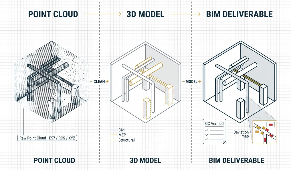
Scan To BIM (Point Cloud to 3D Model)
Convert raw scan data into accurate, structured 3D models meeting LOD standards
Convert raw LiDAR point cloud data into accurate, structured 3D factory models meeting required Level of Detail (LOD) standards. The models are used for layout planning, clash detection, renovation design, equipment procurement and remote facility access eliminating the need for repeated site visits.
Deliverables
- LOD-compliant 3D factory model: Civil, Layout Lines (CLL) · MEP · Structural
- As-built vs design model comparison using Navisworks deviation mapped and documented
- QC using 2D drawings, scan data and panoramic images clash and accuracy verified
- Model delivered in client-preferred format: MicroStation · NX · Inventor · Revit · Recap
- Scan-to-BIM process compliant with global LOD standards (LOD 200 to LOD 400)
Use Case / Client Example
A global automotive OEM required a complete 3D digital record of their assembly hall to support a new model launch planning exercise. CY4 delivered a full LOD 300 MicroStation model covering CLL, MEP and structure layers within 6 weeks of scanning enabling the engineering team to plan line reconfigurations without a single site visit.
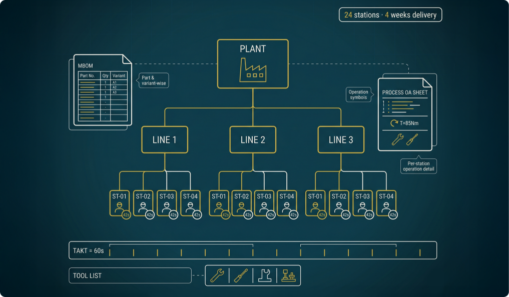
Process Planning
Define and sequence your manufacturing operations from station level to full assembly line
Define and sequence your manufacturing operations from individual station design to full assembly line configuration aligned with your production volume and quality targets. CY4 builds the complete Manufacturing BOM (MBOM) and creates detailed Process OA sheets for every assembly operation.
Deliverables
- Manufacturing BOM (MBOM) part and variant wise for all assembly lines
- Detailed process sequence from station level to plant level
- Station-level layout aligned to process sequence and takt time
- Process OA sheets: operation details, torque standards, tools and fixtures required
- Tool and fixture requirement list aligned to process sequence
Use Case / Client Example
A two-wheeler OEM launching a new EV model needed a complete process plan for a new assembly line before supplier tooling orders were placed. CY4 developed the full MBOM, station sequence and OA sheets for 24 assembly stations in 4 weeks enabling on-time tooling procurement and zero-rework station commissioning.
Simulation (Discrete Event Simulation)
Predict your line's real-world performance before a single machine is installed
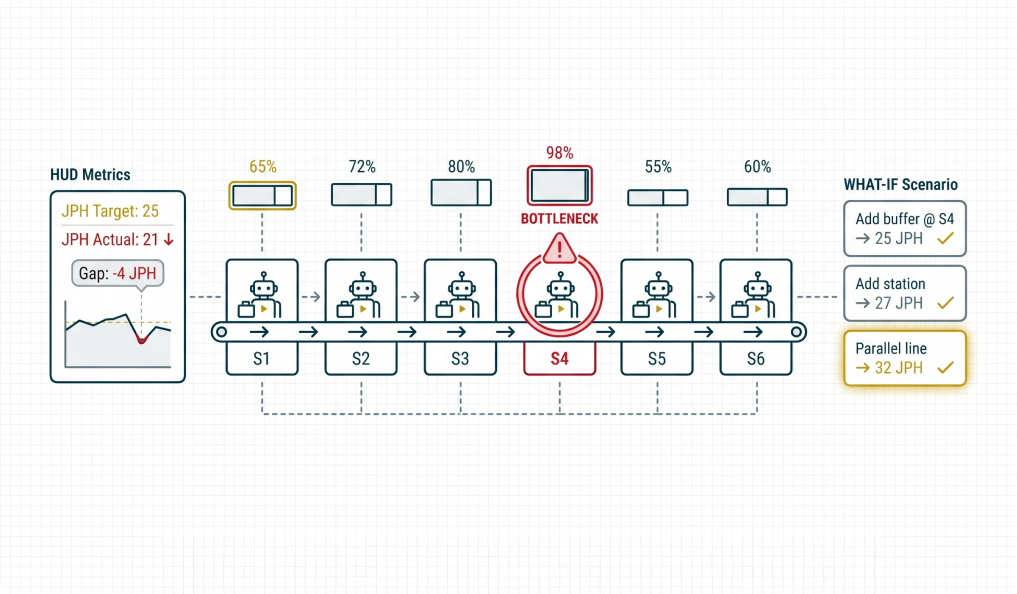
Simulate the real-world behaviour of your entire production system to identify bottlenecks, optimise resource allocation and validate throughput targets before capital is committed to physical implementation.
Deliverables
- Jobs per hour (JPH) analysis against target throughput
- Line and station utilisation percentages identify over and under-loaded stations
- Bottleneck identification ranked by impact on throughput
- Waiting time and buffer size analysis
- Resource allocation optimisation and 'what-if' scenario modelling
Use Case / Client Example
A commercial vehicle OEM needed to validate whether a new chassis assembly line could achieve 25 JPH with the planned station count. CY4's DES model identified that Station 12 would create a recurring bottleneck reducing effective throughput to 21 JPH. Adding a parallel buffer at S12 recovered 4 JPH, saving investment in an additional station.
Dynamic Simulation & Offline Programming (OLP)
Virtually commission your machines and robots before physical installation begins
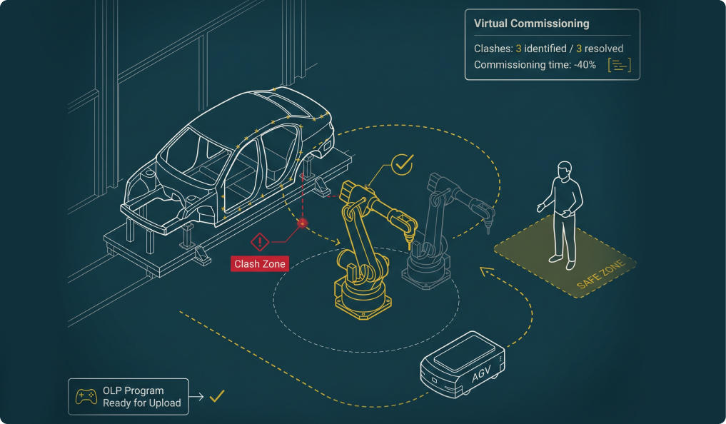
Validate assembly and logistics feasibility through dynamic collision analysis between robots, conveyors and human operators in a fully animated virtual environment. Program virtual PLC logic and run complete virtual commissioning scenarios.
Deliverables
- Manufacturing BOM (MBOM) and detailed process sequence definition
- Man-machine interaction validation operator reach, vision and safety zones
- Dynamic collision analysis: moving objects (robots, AGVs) vs static factory structures
- Robot OLP programs verified and ready for upload to physical controller
- Virtual commissioning report with clash resolution documentation
Use Case / Client Example
An automotive OEM was installing 6 welding robots in an existing body shop with tight clearances. CY4 ran the complete virtual commissioning in Process Simulate identifying 3 dynamic clash zones and adjusting robot paths before any physical installation. Commissioning time was reduced by 40%.
Ergonomic Analysis
Identify unsafe operator movements digitally before workers perform the task
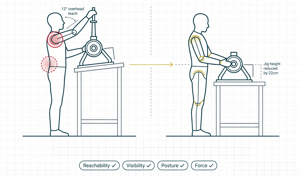
Use digital human simulation to identify and evaluate unsafe or non-ergonomic operator movements for every assembly task. Develop countermeasures in the virtual environment, implement them and validate their effectiveness before asking workers to perform the task physically.
Deliverables
- OWAS posture analysis categorises risk level for each operator movement
- Reachability and visibility checks for all assembly operations
- Safety and ergonomic risk identification ranked by severity and urgency
- Countermeasure proposals: jig height, part orientation, tool weight, assembly sequence
- Before/after validation quantified reduction in ergonomic risk score
Use Case / Client Example
A commercial vehicle OEM identified operators reporting repetitive strain injuries on an axle assembly station. CY4 ran ergonomic analysis using Process Simulate's human module identifying a 12° overhead angle causing OWAS Category 4 risk. Redesigning the jig reduced it to Category 1, eliminating the injury risk before physical changes were made.
Kitting Rack Design
Purpose-designed kitting racks and trolleys optimised before a weld is made
Design kitting racks and trolleys that are optimised for parts visibility, logical arrangement and smooth assembly workflow. Every rack is modelled in full 3D and reviewed against the assembly sequence ensuring the operator can pick the right part at the right time, every time.
Deliverables
- 3D kitting rack model designed to assembly sequence and part dimension requirements
- Parts arrangement layout logical grouping by sub-assembly and pick sequence
- Visibility and access analysis every part reachable without bending or overreaching
- Structural feasibility and load-bearing analysis
- Manufacturing-ready 3D model and 2D drawings for fabrication
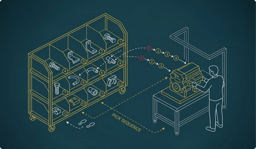
Use Case / Client Example
An EV manufacturer needed kitting racks for a new EV motor assembly line. The existing generic trolleys caused operators to frequently pick wrong parts. CY4 designed purpose-built racks mapped to the exact assembly sequence reducing wrong-pick errors by 85% and cutting search time by 40 seconds per vehicle.